A Model Railway Speedometer
Electronics and build by Jes..
This is a fun DIY project where a couple of small sensors are placed next to a track, to measure a train’s speed. The unit is independent of the layout (i.e. it is not connected to the track & no modifications are required to any rolling stock).
You may end up discovering that you’ve been running your trains a little too fast (especially freight trains)!
A small computer (an Arduino UNO) calculates the time between the sensors which are triggered by rolling stock, converts this time into miles per hour & pops this onto a small liquid crystal (LCD) screen.
It can be set for any gauge & also the distance between the two sensors can be altered (for each of these changes, a simple quick change to the coding is all that's required).
Programming code has to be popped onto the ‘UNO’ - I managed this after watching a few YouTube tutorials & by then gently modifying someone else’s code. I’d never done any coding before.
As I’ve worked out some code, for anyone not keen to tap away at a keyboard, I could just load it onto their UNO. I would just need to know their chosen scale i.e. O, HO, OO, N gauge etc., plus the distance desired between the two sensors (the default distance is 12 inches).
The components to get are:An Arduino UNO (there are lots of clones available nowadays
An LCD screen with an I2C module (which cuts down the wiring to the UNO to just 4 wires). A 4 line, 20 characters per line looks cool.
This is a picture of the I2C module soldered onto the back of the LCD screen:
Two small infra-red sensors (common in the world of model robotics, where they use them as anti-collision sensors).
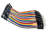
Some jumper wires (sometimes called Dupont wires) to get things up & running quickly. They come pre-wired with male or female ends. For this project, 20cm male to female wires fit the bill. Of course, as good modellers we might permanently wire everything up later in a nice tidy fashion ...
Electronics and build by Jes..
This is a fun DIY project where a couple of small sensors are placed next to a track, to measure a train’s speed. The unit is independent of the layout (i.e. it is not connected to the track & no modifications are required to any rolling stock).
You may end up discovering that you’ve been running your trains a little too fast (especially freight trains)!
A small computer (an Arduino UNO) calculates the time between the sensors which are triggered by rolling stock, converts this time into miles per hour & pops this onto a small liquid crystal (LCD) screen.
It can be set for any gauge & also the distance between the two sensors can be altered (for each of these changes, a simple quick change to the coding is all that's required).
Programming code has to be popped onto the ‘UNO’ - I managed this after watching a few YouTube tutorials & by then gently modifying someone else’s code. I’d never done any coding before.
As I’ve worked out some code, for anyone not keen to tap away at a keyboard, I could just load it onto their UNO. I would just need to know their chosen scale i.e. O, HO, OO, N gauge etc., plus the distance desired between the two sensors (the default distance is 12 inches).
The components to get are:An Arduino UNO (there are lots of clones available nowadays
An LCD screen with an I2C module (which cuts down the wiring to the UNO to just 4 wires). A 4 line, 20 characters per line looks cool.
This is a picture of the I2C module soldered onto the back of the LCD screen:
Two small infra-red sensors (common in the world of model robotics, where they use them as anti-collision sensors).
Some jumper wires (sometimes called Dupont wires) to get things up & running quickly. They come pre-wired with male or female ends. For this project, 20cm male to female wires fit the bill. Of course, as good modellers we might permanently wire everything up later in a nice tidy fashion ...
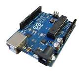
Arduino UNO
|
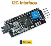
I2C module
|
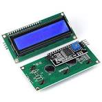
This is a picture of the I2C module soldered onto the back of the LCD screen:
|
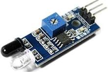
Infra-red sensor
|
Jumper wires (sometimes called Dupont wires)
|
Optional (as you may already have one): A small dc power supply adapter between 7 – 12Volts with the standard 5.5mm outside diameter/2.2mm internal diameter plug fitted (to power the UNO). Later the set up could be permanently wired into the layout’s power system.
Optional (as you may already have one): A USB A to USB B lead (think modern printer lead) if you want to do your own coding/programming of the UNO via your computer:
Optional: 3 LEDs plus a 330ohm resistor for each (as they’ll be powered by the UNO’s 5V outputs). These LEDs are not necessary, but they add to the visual fun by showing what stage the speedometer is at.
I’ll add some pictures separately of my lash up prototype set up to give you an idea of what it looks like.
A wiring diagram is available on request, or you could look at this video which inspired me:
MODEL RAILWAY SPEEDOMETER CODE (Which works in both directions).
Note: All the lines starting '//' are not code.
They're reminder notes or hints to help the idiot Jes when trying to write code.
Version 6f (last updated 18 Feb 2024).
Instructions to import/add the essential libraries to the Arduino UNO.
This allows the Arduino UNO (just 'UNO' hereafter) to communicate with the LCD screen.
// This next line is the library that comes already with the Arduino IDE programming tool.
#include <Wire.h>
// For this next code line to work, need to download an I2C library from the internet.
// Then import the library into the Arduino IDE program's library file.
#include <LiquidCrystal_I2C.h>
// This sets the LCD screen's I2C address (varies with different makes of screen).
// It might for example be '0x3F' instead of '0x27'.
LiquidCrystal_I2C lcd(0x27, 2, 1, 0, 4, 5, 6, 7, 3, POSITIVE);
// Constants
// 'Const int' is a read-only instruction that means it remains constant/can't be varied.
const int WAITING = 1;
const int S_2 = 2;
const int S_3 = 3;
const int READY = 4;
const int stoptime = 5;
// Variables
// Change this number for the distance you want to set between the 2 sensors (in inches).
// Note: The closer the sensors are, the less accurate any speed measurement might be.
float distance = 12.00;
// Change the 'float scale' code for your chosen model scale.
// Here are the common scales:
// O is 43.1, OO or 009 is 76.1, HO is 87.1, the new TT is 120.1
// UK N is 148.1 & European/American N is 160.1
float scale = 148.1;
float starttime, finish, elapsed, miles, hours, mph, scaleMPH;
// These set where the infra-red sensors plug into the numbered pins on the UNO board.
// Left sensor uses pin 8 on UNO board.
int sensorLeft = 8;
// Right sensor uses pin 9 on UNO board.
int sensorRight = 9;
int leftValue;
int rightValue;
int var = READY;
// These set where the LEDs plug into the numbered pins on the UNO board.
// Pin 11 for the green 'Ready' LED.
int ledReady = 11;
// Pin 12 for the yellow 'Measuring' LED.
int ledMeasuring = 12;
// Pin 13 for the red 'Reset' LED.
int ledReset = 13;
void setup() {
// Put your setup code here, to run once:
// Tells the UNO that pins 8 & 9 are Inputs from the sensors.
pinMode(sensorLeft, INPUT);
pinMode(sensorRight, INPUT);
// Tells the UNO that pins 11, 12 & 13 are Outputs to the LEDs.
// Pin 11 (green 'ready' LED).
pinMode(ledReady, OUTPUT);
// Pin 12 (yellow 'measuring' LED).
pinMode(ledMeasuring, OUTPUT);
// Pin 13 (red 'reset' LED).
pinMode(ledReset, OUTPUT);
// To initialise an 80 character LCD screen, type: (20, 4).
// (assuming 20 characters on each of the 4 lines).
// Alternatively, for a 32 character LCD screen, type: (16, 2).
// (assuming 16 characters on each of the 2 lines).
lcd.begin(20, 4);
// To turn the LCD screen backlight on.
lcd.backlight();
lcd.clear();
}
void loop() {
// put your main code here, to run repeatedly:
switch (var) {
// Next line - note that this is a colon at the end (cf. the usual semi-colon).
// Now the start up 'ready' screen will be set up.
case READY:
lcd.clear();
// Next is placing characters on the LCD screen.
// i.e. how far along & down each of the lines, each line having 20 or 16 characters max.
// Hint: So for an 80 character screen:
// Horizontal lines are numbered 0 - 19
// Vertical columns are numbered 0 - 3
// So top left on the screen is horizontal line 0 followed by vertical column 0.
// Thus bottom right on the screen is horizontal line 19 followed by vertical column 3.
// First line of the start up screen to have 'MODEL RAILWAY' written on it.
lcd.setCursor(3,0);
lcd.print("MODEL RAILWAY");
// Second line of the start up screen to have 'SPEEDOMETER' written on it.
lcd.setCursor(4,1);
lcd.print("SPEEDOMETER");
// Third line of start up screen to have 'READY...' written on it
lcd.setCursor(7,2);
lcd.print("READY...");
var = WAITING;
// Next line - turns off pin 13 (red 'reset' LED), for the start up screen.
digitalWrite(ledReset, LOW);
// Next line - turns on pin 10 (green 'ready' LED), for start up screen.
digitalWrite(ledReady, HIGH);
break;
// Next line - note that this is a colon at the end (cf. the usual semi-colon).
case WAITING:
// Sets up the left & right sensors (either can be the first to be tripped).
leftValue = digitalRead(sensorLeft);
if (leftValue == 0) {
starttime = millis();
lcd.clear ();
lcd.setCursor(2, 1);
lcd.print("MEASURING SPEED...");
var = S_2;
// Next line - turns off pin 11 (green 'ready' LED), when 1st sensor is tripped.
digitalWrite(ledReady, LOW);
// Next line - turns on pin 12 (yellow 'measuring' LED), when 1st sensor is tripped.
digitalWrite(ledMeasuring, HIGH);
}
rightValue = digitalRead(sensorRight);
if (rightValue == 0) {
starttime = millis();
lcd.clear ();
lcd.setCursor(2, 1);
lcd.print("MEASURING SPEED...");
var = S_3;
// Next line - turns off pin 11 (green 'ready' LED), when 1st sensor is tripped.
digitalWrite(ledReady, LOW);
// Next line - turns on pin 12 (yellow 'measuring' LED), when 1st sensor is tripped.
digitalWrite(ledMeasuring, HIGH);
}
break;
// Sets up the left & right sensors (either can be the second to be tripped).
// Next line - note that this is a colon at the end (cf. the usual semi-colon).
case S_2:
rightValue = digitalRead(sensorRight);
if (rightValue == 0) {
finish = millis();
var = stoptime;
// Next line - turns off pin 12 (yellow 'measuring' LED), when 2nd sensor is tripped.
digitalWrite(ledMeasuring, LOW);
// Next line - turns on pin 13 (red 'reset' LED), when 2nd sensor is tripped.
digitalWrite(ledReset, HIGH);
}
break;
// Next line - note that this is a colon at the end (cf. the more usual semi-colon).
case S_3:
leftValue = digitalRead(sensorLeft);
if (leftValue == 0) {
finish = millis();
var = stoptime;
// Next line - turns off pin 12 (yellow 'measuring' LED), when 2nd sensor is tripped.
digitalWrite(ledMeasuring, LOW);
// Next line - turns on pin 13 (red 'reset' LED), when 2nd sensor is tripped.
digitalWrite(ledReset, HIGH);
}
break;
// Converting the UNO's milliseconds to hours & the UNO's inches to miles.
// Next line - note that this is a colon at the end (cf. the more usual semi-colon).
case stoptime:
// Next line is time in milliseconds (the default way an Arduino UNO measures time).
elapsed = finish - starttime;
// Next line - time now set to seconds (i.e. 1000 milliseconds in one second).
elapsed = elapsed / 1000;
// Next line - time now set to hours (i.e. 3600 seconds in one hour).
hours = elapsed / 3600;
// Next line - to set miles (i.e. 63360 inches in one mile).
miles = distance / 63360;
mph = miles / hours;
scaleMPH = mph * scale;
// Sets up where the resetting message & speed appear on the LCD screen.
lcd.clear();
lcd.setCursor(0, 0);
lcd.print("DONE, NOW RESETTING.");
lcd.setCursor(5, 3);
lcd.print(scaleMPH);
lcd.setCursor(12, 3);
lcd.print("MPH");
lcd.setCursor(8, 0);
// Next, set the delay/reset time before system is ready to start again.
// Each 1000 = one second (1000 milliseconds to one second).
// It may need increasing for long slow trains?
// eg. consider (30000) which would be 30 seconds - to allow a slow freight train to pass?
delay(30000);
// Now to complete the loop, by returning to the start up 'ready' state & screen.
var = READY;
break;
// Finally, two curly braces/brackets required to balance & end input to code.
}}
